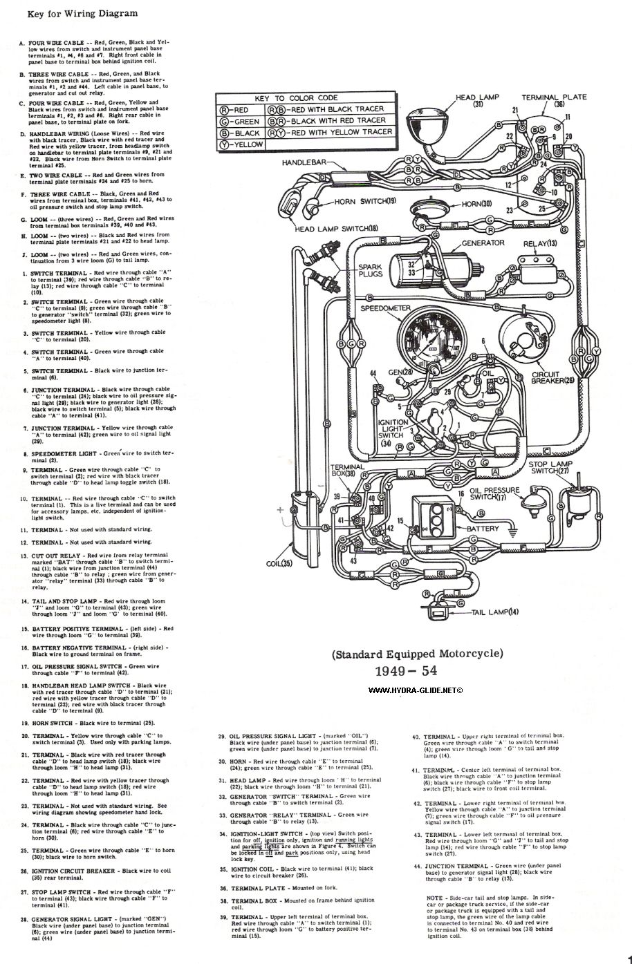
The rear terminal (#33) on a 3-brush is the "RELAY" terminal which in other systems could also be called the "GEN" or "ARMATURE" terminal, this is where the power comes out of the generator. It connects to the outboard end of the relay, the one with the single terminal.
The front terminal (#32) on a 32E 3-brush is actually a "FIELD" terminal, if the ID tag is still on the generator it will say "SWITCH". There are 2 Field coils in a 32E, one is connected to the 3rd brush and is always active, the 2nd field coil recieves power ONLY when the ignition switch is in the "LIGHTS" postion, this energizes the 2nd field and increases the output of the generator.
So, make sure you know what type of generator you actually have, a 2-brush with a regulator, or a 3-brush with a relay, they are entirely different animals and you can not wire them the same way. (you can't connect a regulator to a 3-brush, you cannot connect a 2-brush to a relay)
The wiring is the same for Pans and 45". The horn and all other electrical components are the same , only the location of certain wires and components may differ slightly.
